

What it took to make a simple-looking injection molded part look clean, feel solid, and come out of the mold.
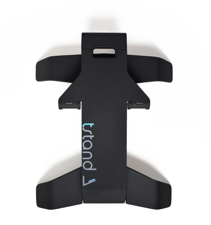
Tstand looks simple. It is a tablet stand that rests on your chest while you lie in bed or on the couch, so you can watch a movie without holding the device or craning your neck. On a render, its base is a clean black shape with nothing to explain. Getting that clean shape into production took more mechanical engineering than the surface suggests.
Before we get into the product design challenges, it helps to understand what the product is, what the base does, and why its shape and strength matter so much.
What Tstand Is: A Hands-Free Tablet Stand Designed Around the Body
Tstand is a tablet and iPad holder that we designed and developed in-house for watching while lying down. Instead of propping a tablet on a pillow or holding it at arm’s length, you rest Tstand on your chest and the tablet is held above you at a comfortable viewing distance and angle. Your hands are free and your neck stays relaxed.


The base: the part that rests on the chest
Tstand has two main elements: an arm that holds the tablet, and the base it rises from. The base is the part that touches the user. It lies on the chest, and the arm and tablet are carried above it. Almost everything the user feels about the product, including stability, comfort, and perceived quality, comes through the base.
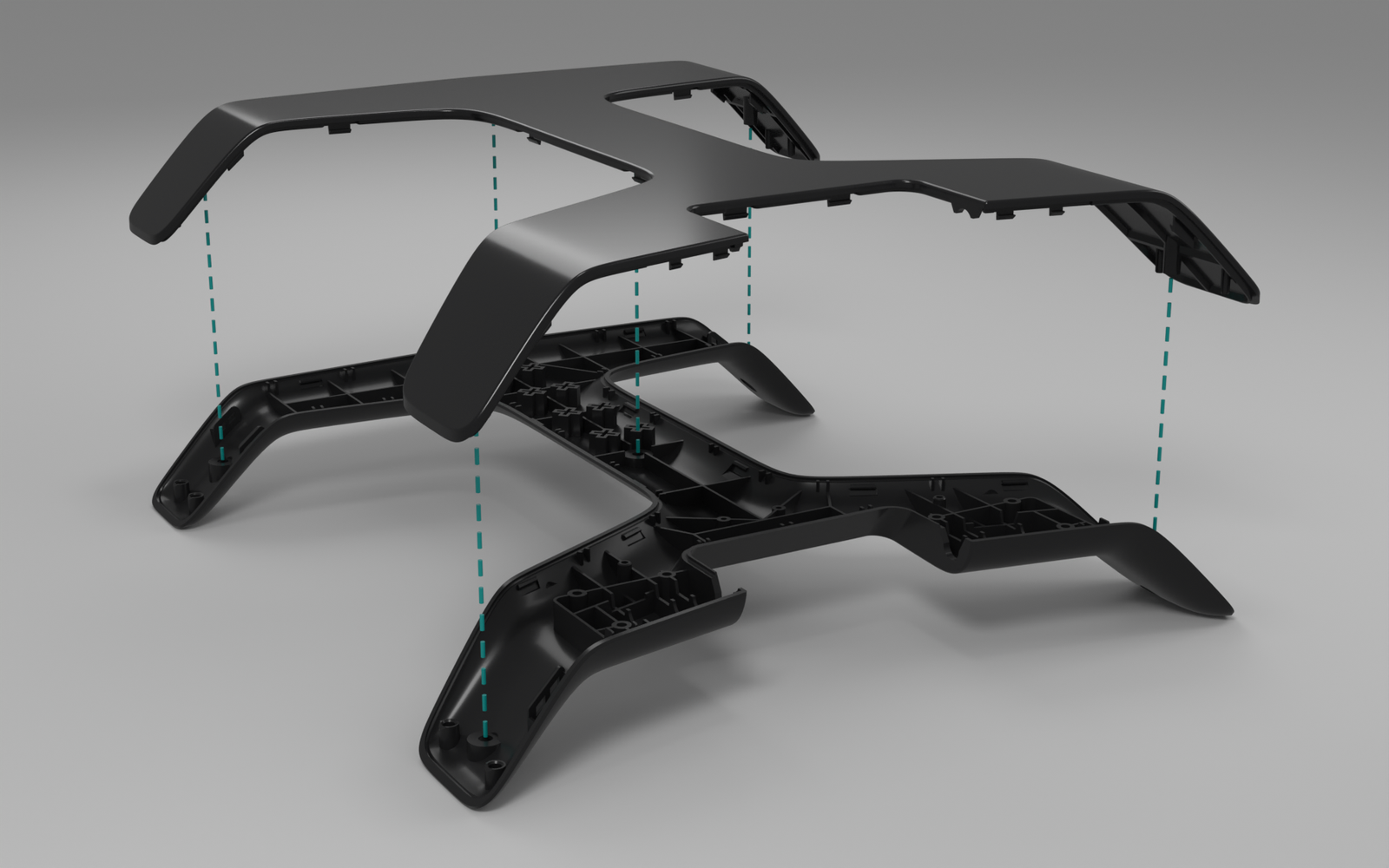
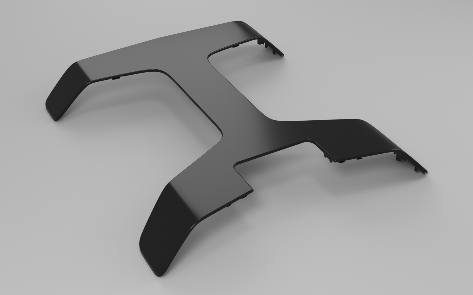
Mechanically, the base is two injection molded plastic halves, a cosmetic top and a structural bottom, that snap and screw together around a metal insert. The top half carries the surface the user sees and touches. The bottom half carries most of the structure: screw bosses, ribs, and locating features. That split is common in consumer product development because it lets each part do one job well, but it also means the quality of the product depends on how well the two halves are designed, molded, and assembled together.
Why the base has to be stable and strong
The base sits on a surface that moves and breathes. It carries the weight of the arm and tablet, and it takes every shift the user makes: reaching for the screen, adjusting the angle, turning slightly, or laughing at a scene. It has to handle all of that without rocking, flexing, or creaking, and without the seam between its two halves opening. Because it sits against skin and clothing, it also has to be smooth and quiet.
These requirements are qualitative, but they are unforgiving. People notice immediately when something resting on their body feels loose. They drove most of the engineering decisions in this article, especially the snap-fit redesign of the joint between the two halves.
Why an uppercase H: an ergonomic, inclusive footprint
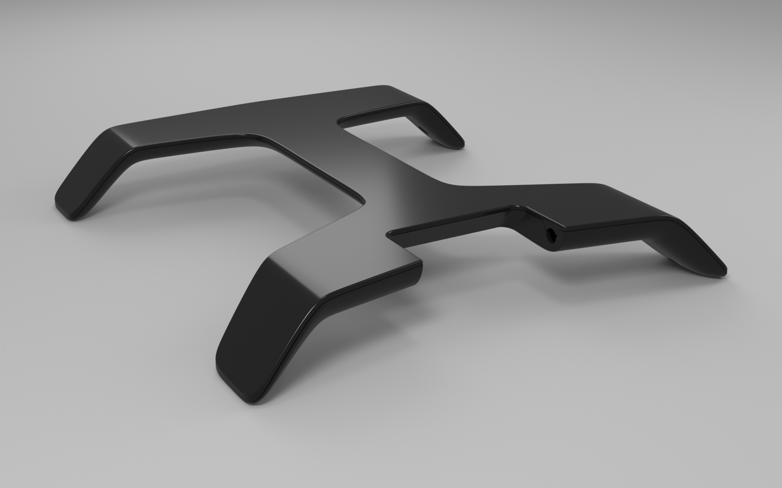
Seen from above, the base is shaped like an uppercase letter H. The centre bar of the H runs along the sternum, and the two end bars rest across the upper chest and the lower rib cage. The open spaces on either side of the centre bar clear the chest instead of pressing on it.
That shape is deliberate. A solid, flat footprint would bear on the softest and highest points of the chest and tend to rock. The H shape rests on the firmer structure of the sternum and ribs and leaves room on either side of the centre bar, so the base sits comfortably and stays put on a wide range of body types, including women with larger busts. It is an ergonomic choice and an inclusive one: the product fits the people using it, rather than asking them to fit the product.
The shape also has consequences for mechanical engineering. An H-shaped footprint means long, narrow arms, angled feet with cosmetic faces, and seams that run a long way between fasteners. Those features set up the three product design challenges below: sink marks on the cosmetic top, a screw-only joint that was not sturdy enough, and the mold tooling, specifically lifters, needed to form the snap-fit undercuts that fixed it.
Along the way, we point out where these problems show up in other plastic products, because none of them are unique to Tstand. If you are taking a product from prototyping to production, these are the kinds of design for manufacturing (DFM) details that decide whether your first production parts look like your renders.
Challenge 1: Sink Marks on the Cosmetic Top Half
What we saw
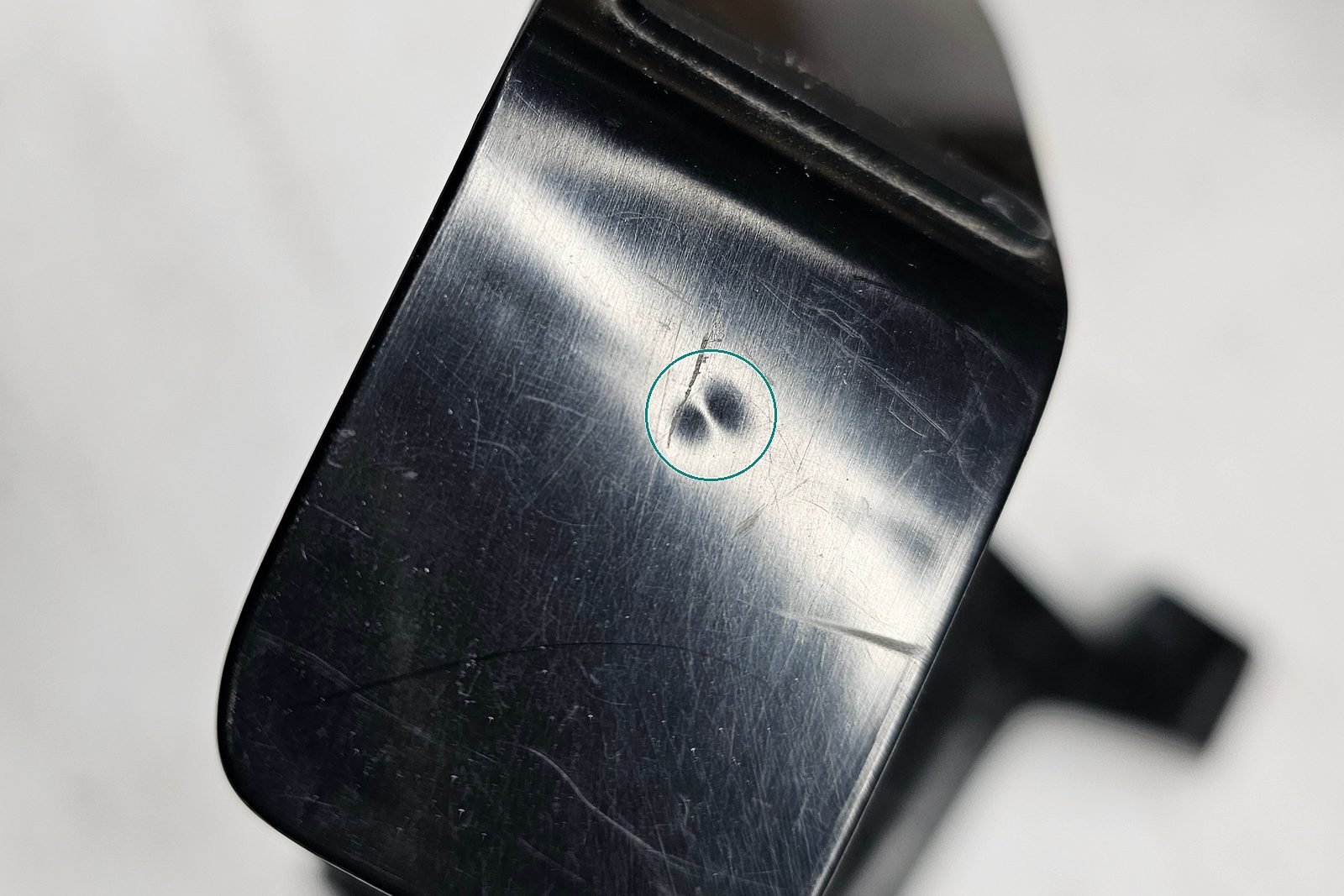
Early molded parts showed circular dimples on the angled faces of the feet. They were small, but on a glossy black surface under room light they were easy to see. They also sat in exactly the place a user’s eye lands when picking the stand up.
Why it happened
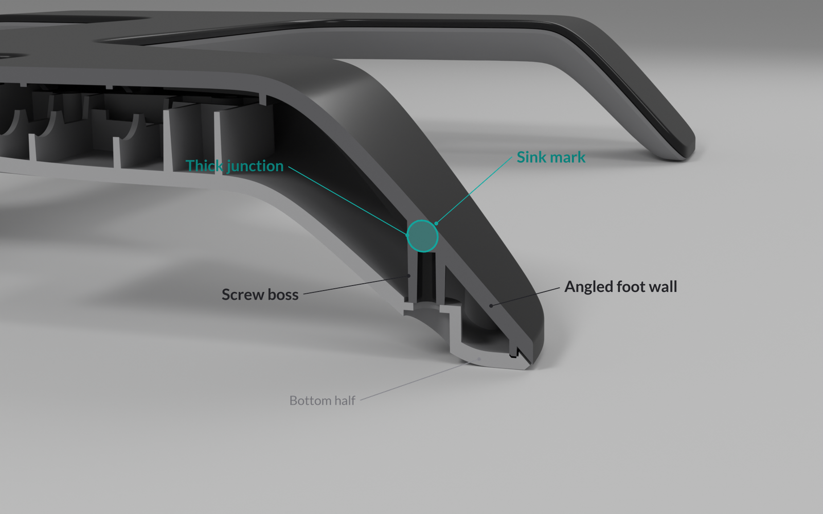
Sink marks are one of the most common injection molding defects, and the cause is almost always the same: local thick sections. Plastic shrinks as it cools. Thin walls freeze quickly and evenly. Where a thick section meets a thinner wall, the core of that thick section stays molten longer. As it finally cools and shrinks, it pulls on the surface that has already formed, and the surface dimples inward.
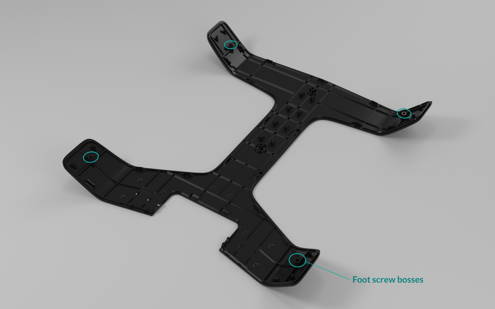
On the Tstand top half, the thick sections were the junctions where screw bosses meet the inside of the angled foot walls. The nominal wall was about 2.2 mm. Where the boss joined that wall, the effective section was noticeably thicker, so that zone cooled more slowly than the wall around it. The result was a sink mark directly above each boss, on the outside face of the foot.
Why process changes were not enough
The first response to sink is usually process: more pack pressure, longer hold time, a cooler mold, a slower cooling cycle. These levers can reduce sink, and they are worth trying because they cost nothing in steel. On Tstand, they were not enough to make the dimples disappear on a glossy cosmetic face.
This is a pattern we see across the industry. Process tuning can push material into a shrinking section, but it cannot change the fact that one section of the part is thicker than its neighbours. Pushing harder also has side effects, such as higher molded-in stress, flash, or longer cycle times. When the cause is geometry, the durable fix is usually geometry.
The fix: +0.25 mm of wall thickness
The manufacturer resolved the sink by adding about 0.25 mm of wall thickness across the top of the top-base part. That small change shifted the balance between the wall and the boss junctions beneath it. With a slightly thicker wall, the cosmetic skin was better able to resist the pull of the cooling junction behind it, and the dimples no longer read on the surface.
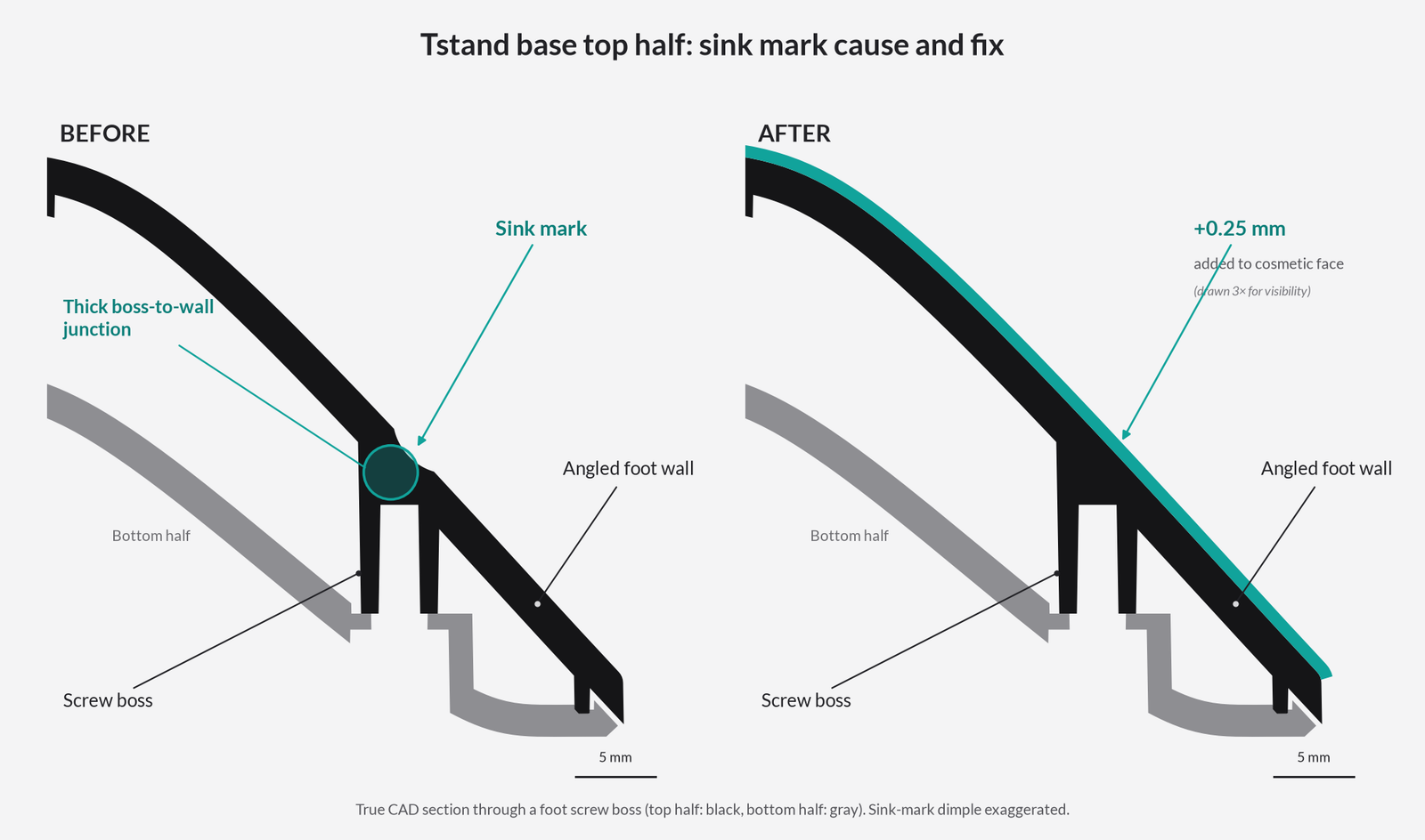
The change was made where it mattered, on the cosmetic face, and it did not require moving the bosses or changing how the halves assemble.
The broader lesson on sink marks
Sink tends to appear wherever thick features sit behind a visible surface. Common examples include:
- Screw bosses under a cosmetic wall, as on Tstand. Typical design for manufacturing (DFM) responses include coring out the boss, connecting it to the wall with thinner gussets, or offsetting it from the visible face.
- Ribs that are too thick relative to the wall. A rib that matches the wall thickness will often show a line of sink on the opposite face. Ribs are generally designed thinner than the wall they support for this reason.
- Thick transitions and solid corners. Anywhere material collects, it cools last and pulls on whatever is around it.
- Surface finish choices. Gloss and dark colours make sink more visible. A texture can hide minor sink, but it changes the look of the product.
The right fix depends on what the part has to do and what it has to look like. On Tstand, the cosmetic finish and the boss positions were fixed priorities, so a small wall-thickness change was the cleanest path.
Challenge 2: A Screw-Only Joint Was Not Sturdy Enough
The problem with six screws
The first assembly approach joined the two halves with six screws. On paper, that sounds sufficient. In hand, it was not. Six screws clamp the halves together at six points, and the long, narrow arms of the H-shaped base leave a lot of seam between those points. Between screws, the seam could open slightly, and the halves could flex and twist relative to each other.
For a product that rests on someone’s chest, that matters. A joint that moves can creak, show a gap, or feel cheap. And because the top half is the cosmetic surface, any gap at the seam is visible.
The redesign: 19 cantilever snap-fits
Our engineering team redesigned the joint by adding 19 cantilever snap-fits around the perimeter and along the spine of the base. Each snap is a flexible beam with a hook on the top half that locks under a catch ledge molded into the bottom half. The six screws stayed.
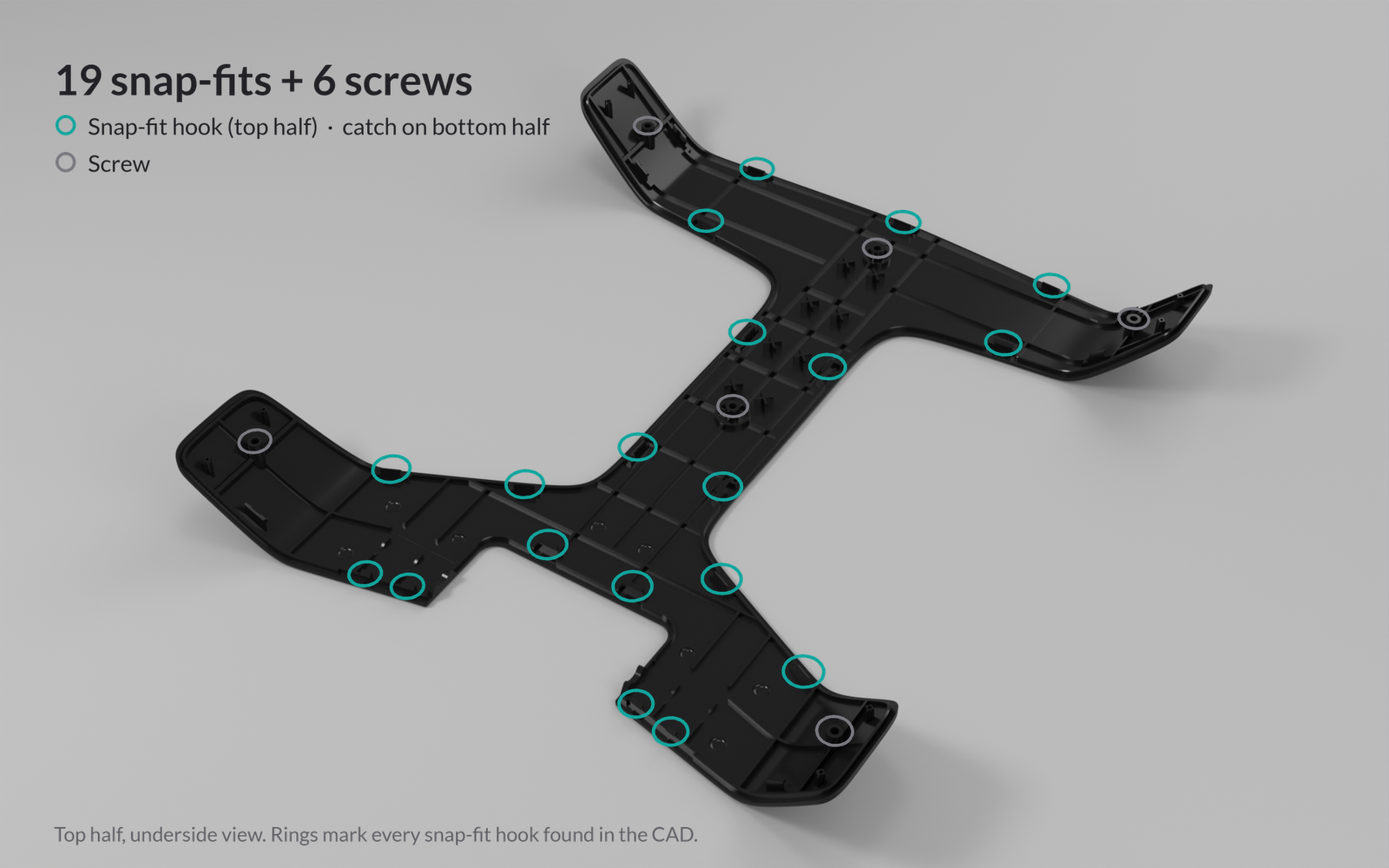
The two features now do different jobs. The screws provide the clamping force. The snaps hold the seam closed between the screws and keep the halves registered to each other around the whole outline. CAD shows a small amount of axial play at the retention face, so the snaps are locating and retaining the halves rather than clamping them; the screws take up that clamping load.
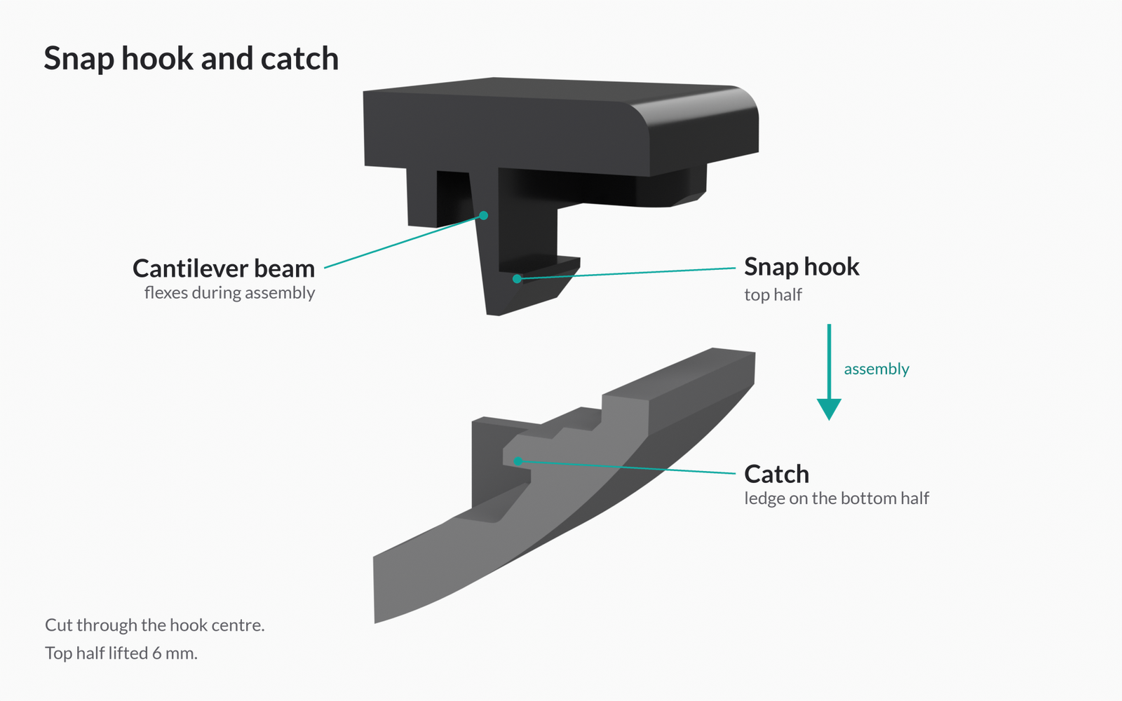
How each snap works
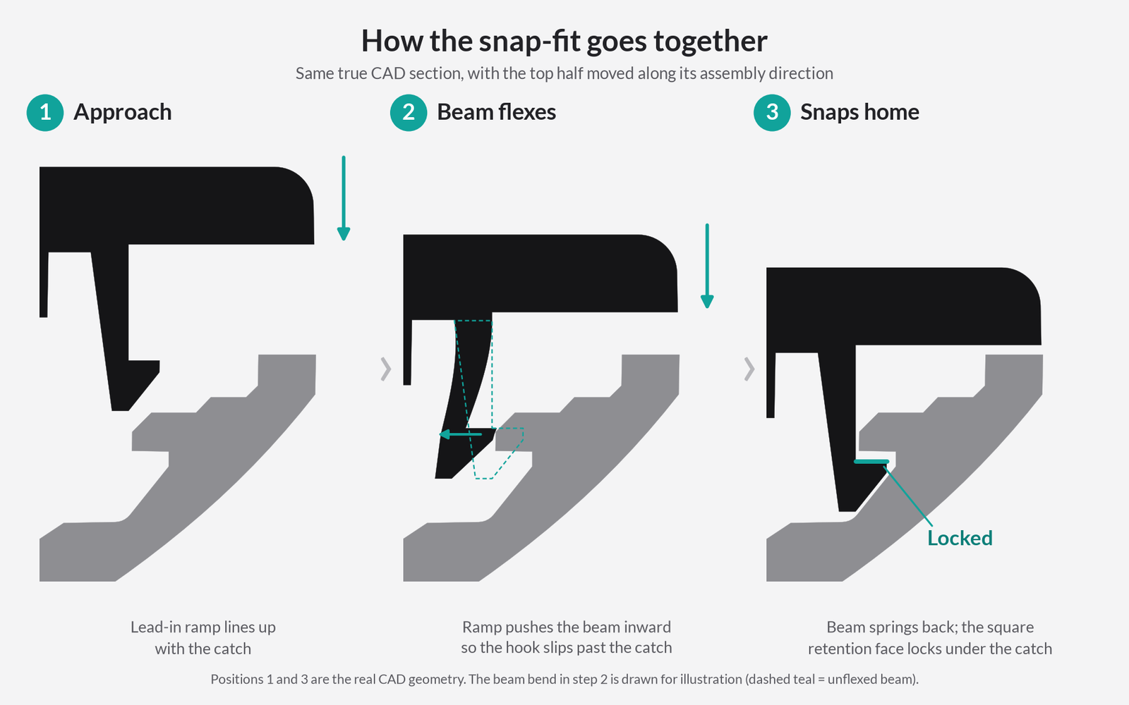
A cantilever snap-fit relies on controlled flex. As the top half is pressed down, the angled lead-in on the hook meets the catch and deflects the beam. Once the hook passes the ledge, the beam springs back and the square retention face sits under the catch. Pulling the halves apart would require the beam to deflect in a direction it is not designed to go.
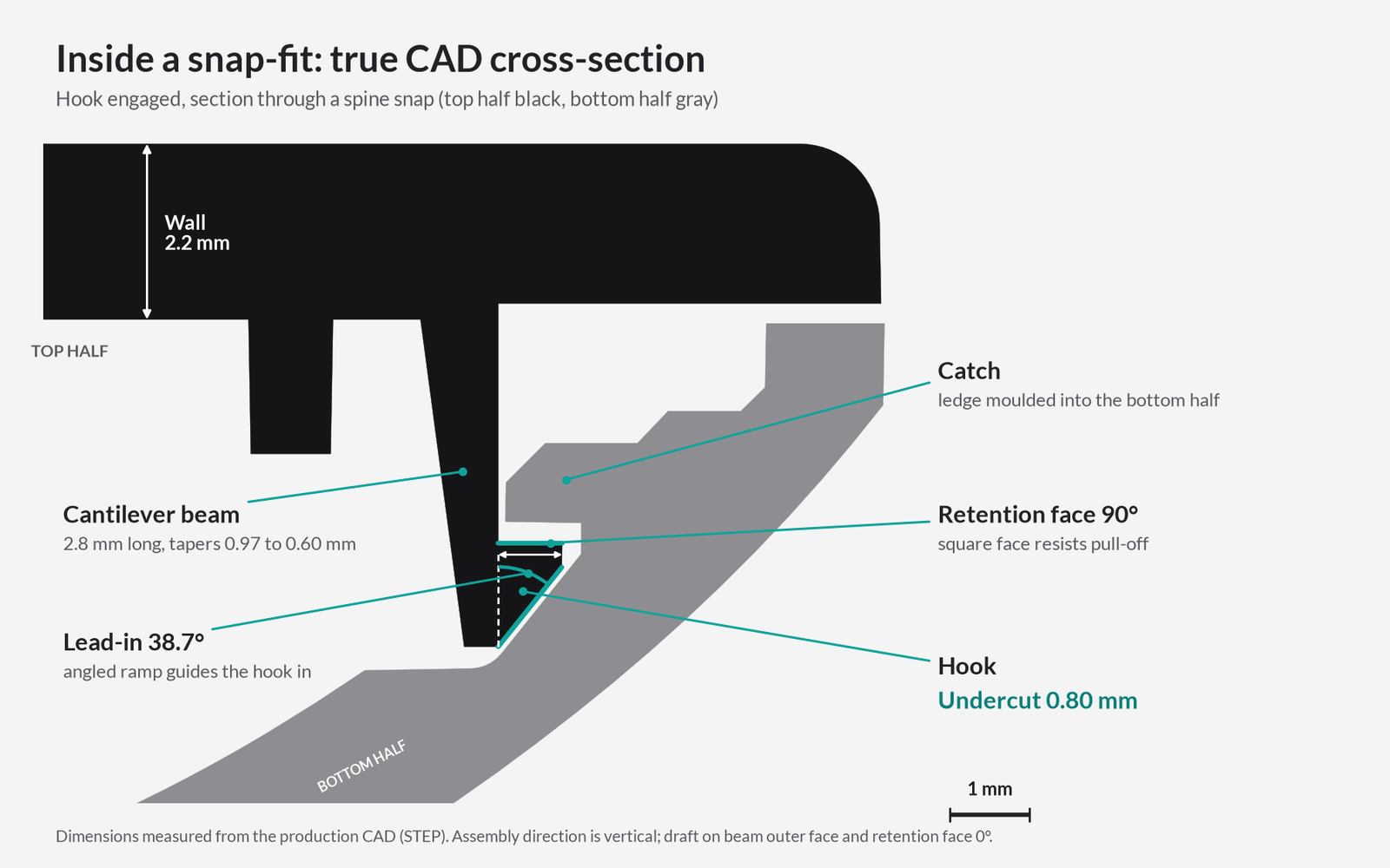
The geometry of the beam, the lead-in angle, and the depth of the undercut are a balance, as the Covestro snap-fit design guide explains in detail. Too stiff, and the snap is hard to assemble or overstrains the plastic. Too flexible, and it will not hold. These values are set in CAD and confirmed on prototype and first-article parts, because the real behaviour depends on the molded material and the part as molded.
Why screws plus snaps beat screws alone
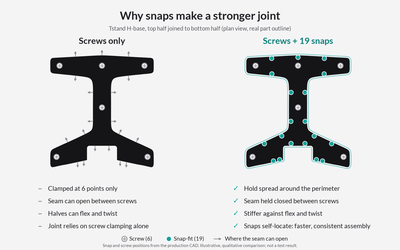
With screws alone, the joint relies on six clamping points. With snaps added, the hold is spread around the perimeter, the seam stays closed between screws, and the assembly is stiffer against flex and twist. The snaps also self-locate the halves, which makes assembly faster and more consistent.
Where else this pattern shows up
Pairing snaps with screws is a familiar move in plastic enclosure design. Remote controls, handheld device housings, and appliance covers often use a handful of screws for clamping and serviceability, with snaps or interlocking lips around the edge to keep long seams closed. When a two-part housing shows a gap or creaks between fasteners, adding more screws is one option, but it adds parts, assembly time, and visible fastener locations. Distributing the hold with snap-fits is often the cleaner answer, as long as the tooling can produce them.
That last condition is where the next challenge starts.
Challenge 3: Lifters to Mold the Snap Undercuts
Why snaps create a tooling problem
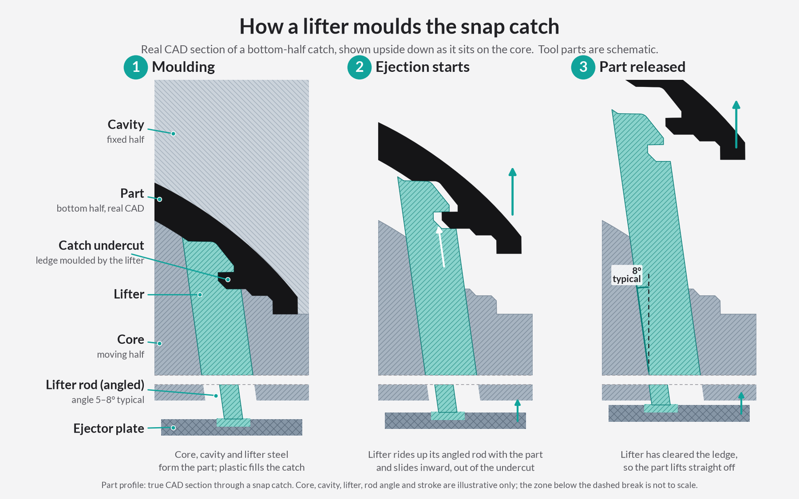
An injection mold opens in one direction. The cavity side pulls away, and ejector pins push the part off the core. Any feature that would catch on the steel as the part comes off in that direction is called an undercut.
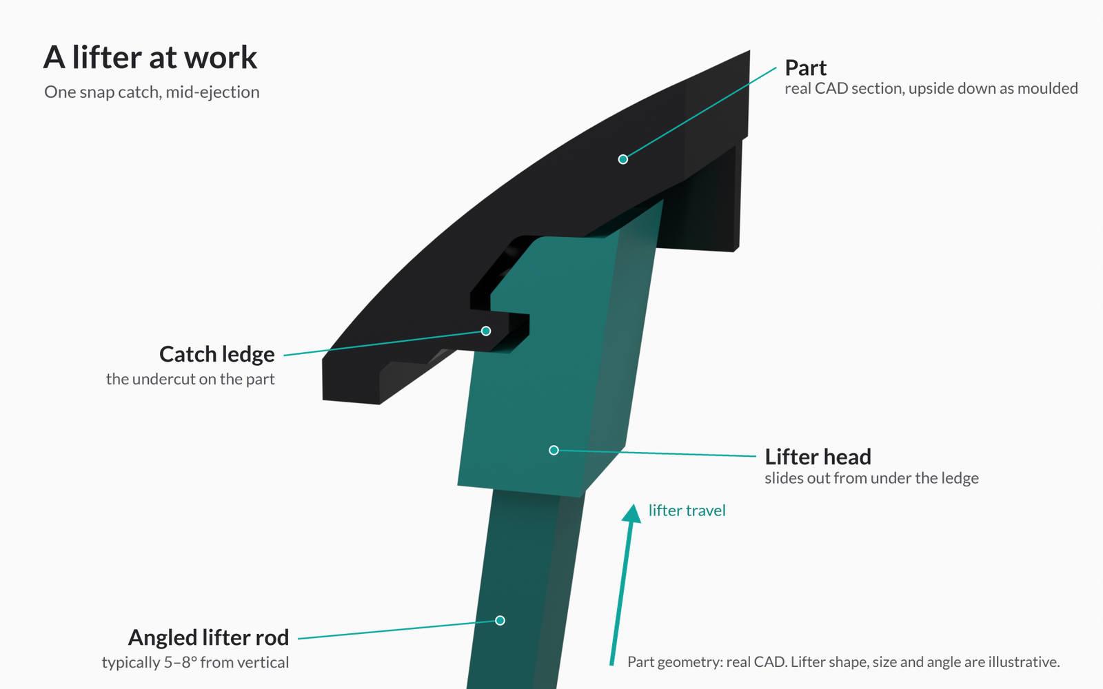
The catch ledges on the Tstand bottom half are undercuts by design. That overhang is exactly what the snap hooks lock under. If the mold were solid steel under each ledge, the part would be trapped on the core. So each ledge needs a piece of tooling that can form it and then get out of the way.
How a lifter works
On the bottom-half tool, the catch ledges are formed with lifters. A lifter is a steel insert mounted on an angled rod. During molding, the lifter head sits in the core and forms the underside of the ledge. When the mold opens and the ejector plate moves forward, the angled rod drives the lifter up with the part and, because of the angle, sideways at the same time. That sideways travel slides the lifter head out from under the ledge. By the time the part is fully ejected, the lifter has cleared the undercut and the part lifts straight off.
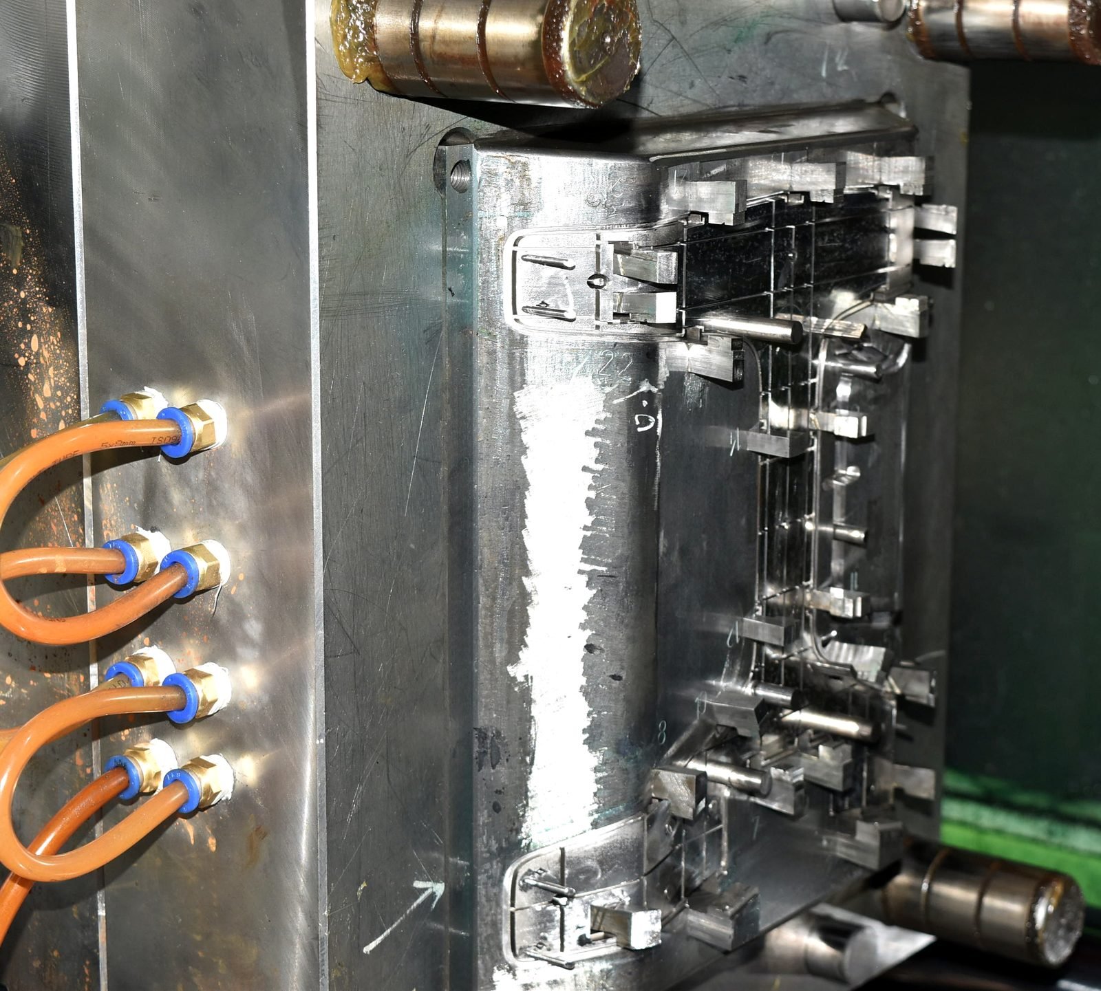
One lifter per catch
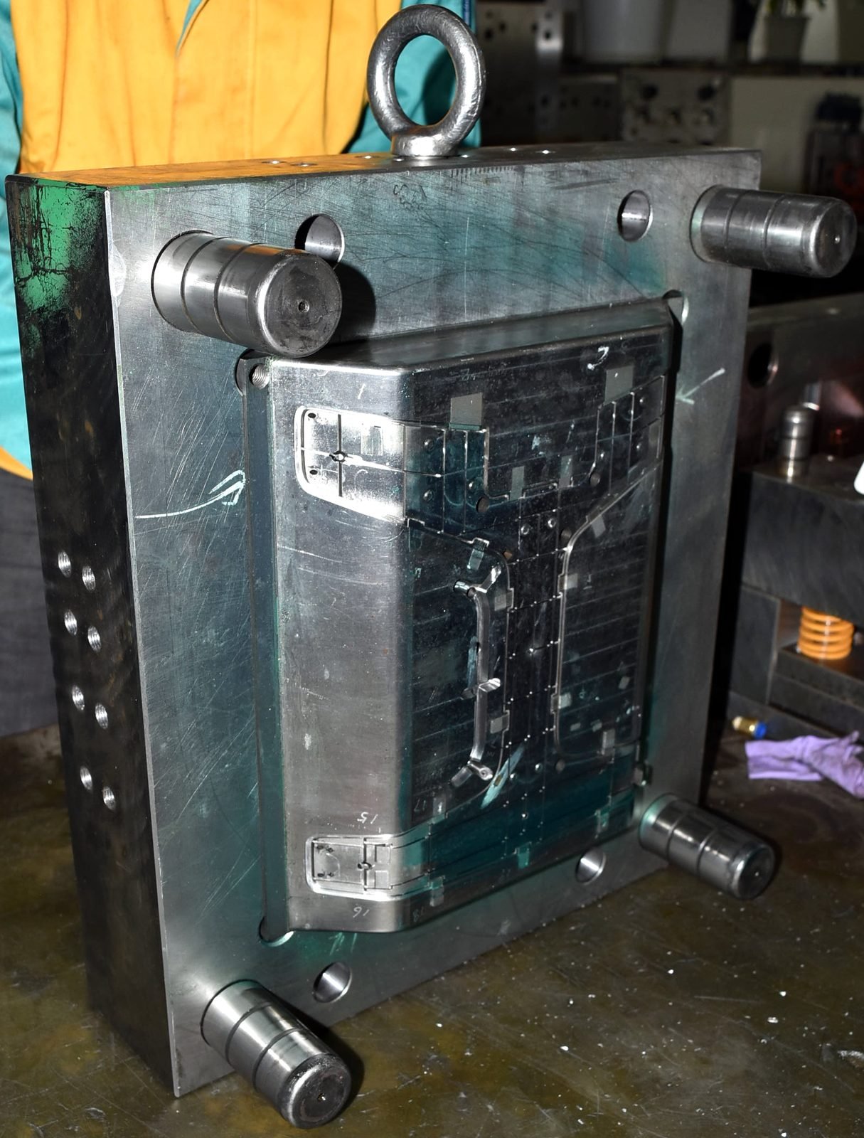
Because each catch faces its own direction, each needs its own lifter travelling away from its own ledge. On the Tstand bottom half, that means one lifter per snap catch, or 19 lifters in the tool.
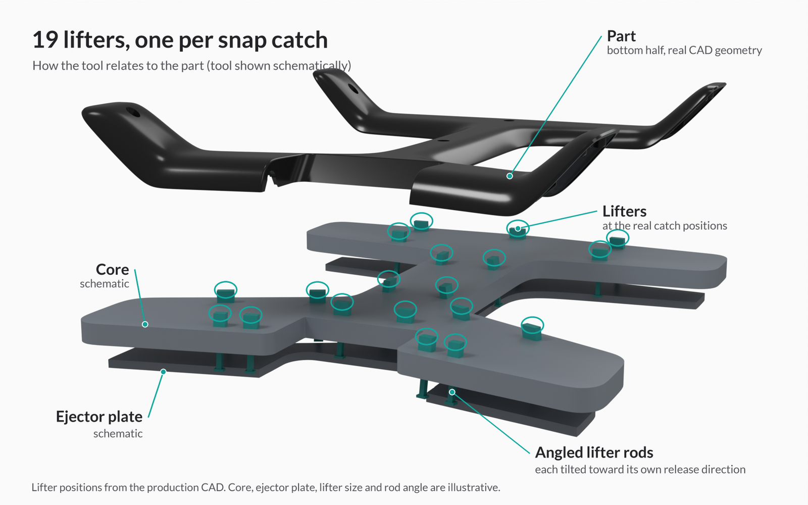
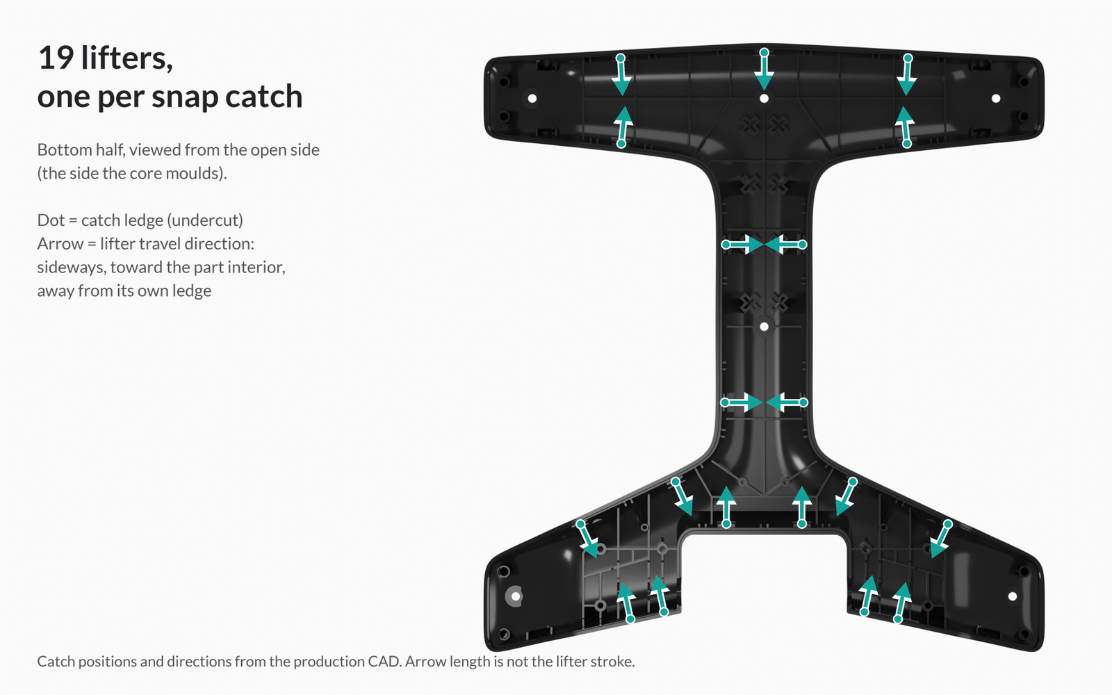
There is some room for toolmaker judgment here. Four of the catches near the notch ends share two long ledges, so a toolmaker could form each pair with a single longer lifter and build the tool with 17 lifters instead of 19. That kind of decision is typically made during mold design, with input from the toolmaker on cost, cooling, and maintenance.
The hooks on the top half are also undercuts and need their own release features in that tool. We have focused here on the catch lifters in the bottom-half tool, since they are the most direct consequence of the snap redesign.
What this means for cost and timing
Lifters are standard tooling, but they are not free. Each one adds machining, fitting, and moving steel that needs to be maintained. They also take space under the part that would otherwise be available for cooling lines and ejector pins. This is why snap-fit design and mold design have to happen together. A snap that is easy to draw in CAD can be expensive, or impossible, to mold if its undercut has no clear release path.
For early prototyping, teams often avoid this by 3D printing parts or using soft tooling or bridge tooling with hand-loaded inserts in place of lifters. Those are useful for validating fit and feel. But the production tool is where the lifter design, release angles, and clearances have to be right, and pilot parts are where you confirm that every snap forms cleanly and every lifter clears.
Design, Tooling, and Assembly Are One Problem
None of these three challenges stood alone. The sink marks came from bosses that exist to hold screws. The screws alone were not enough, which led to snap-fits. The snap-fits created undercuts, which required lifters in the mold. A change in one place carried through the part, the tool, and the assembly line.
That is the reality of product development for injection molded products. A part can look finished in CAD and still need this depth of mechanical engineering and DFM work before it ships sturdy and cosmetically clean. The most efficient way through is to treat industrial design, part design, mold design, and assembly as a single conversation from the start, and to use prototypes, first-article inspection, and pilot runs to confirm decisions before production volumes depend on them.
Tstand is a simple product to use. Making it that way took careful attention to wall thickness, joint design, and tooling. That is the kind of work we enjoy most, and the kind we bring to every product we help take to production.